
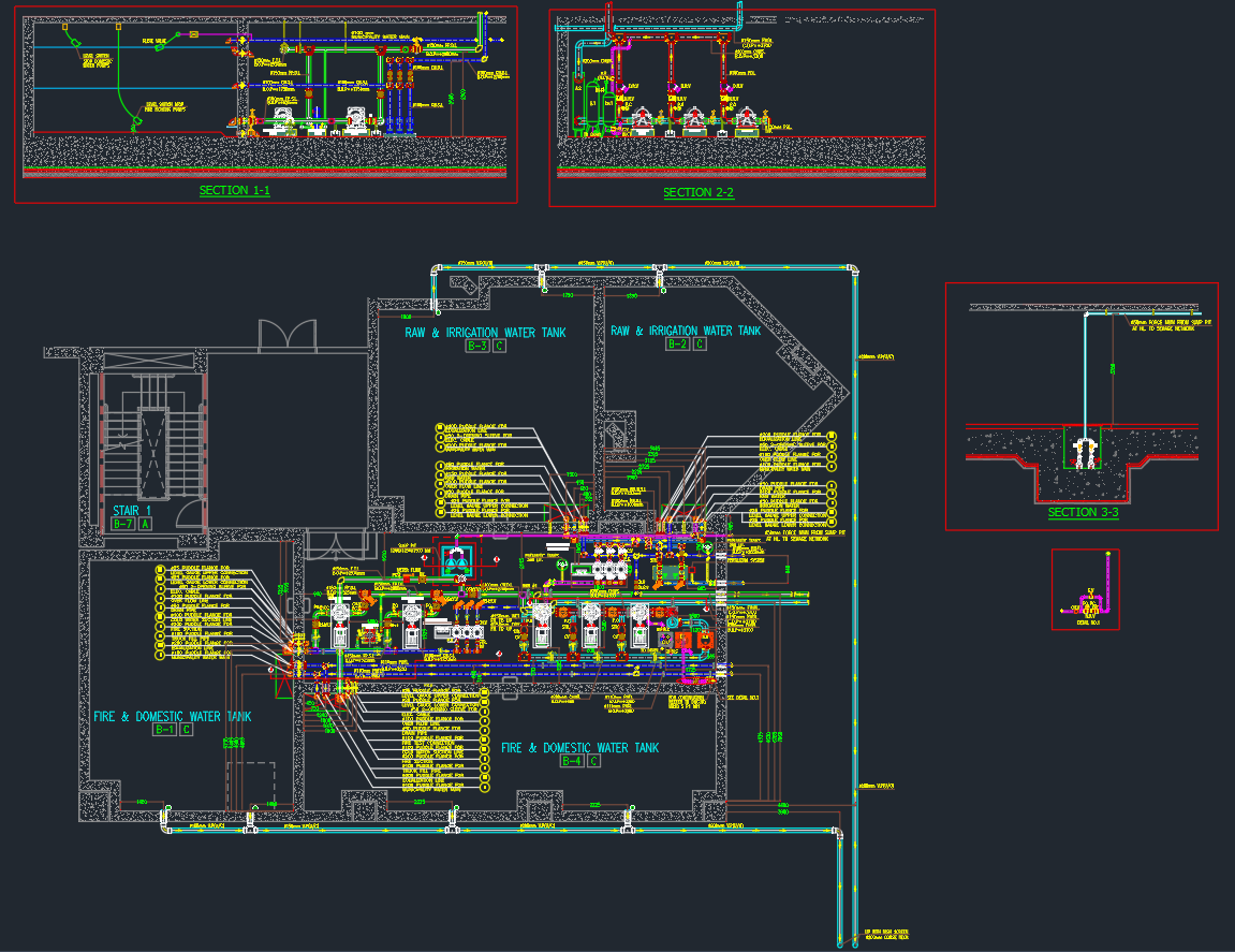
This detailed CAD drawing presents the water tank and pump room layout, essential for designing building water storage and pumping systems. It provides a clear and scalable framework for mechanical engineers, architects, and contractors involved in water supply infrastructure. The drawing assists in visualizing system arrangements, pipe connections, and equipment placement, supporting accurate planning and installation.
Preview Images
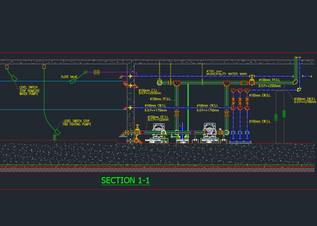
What the drawing includes
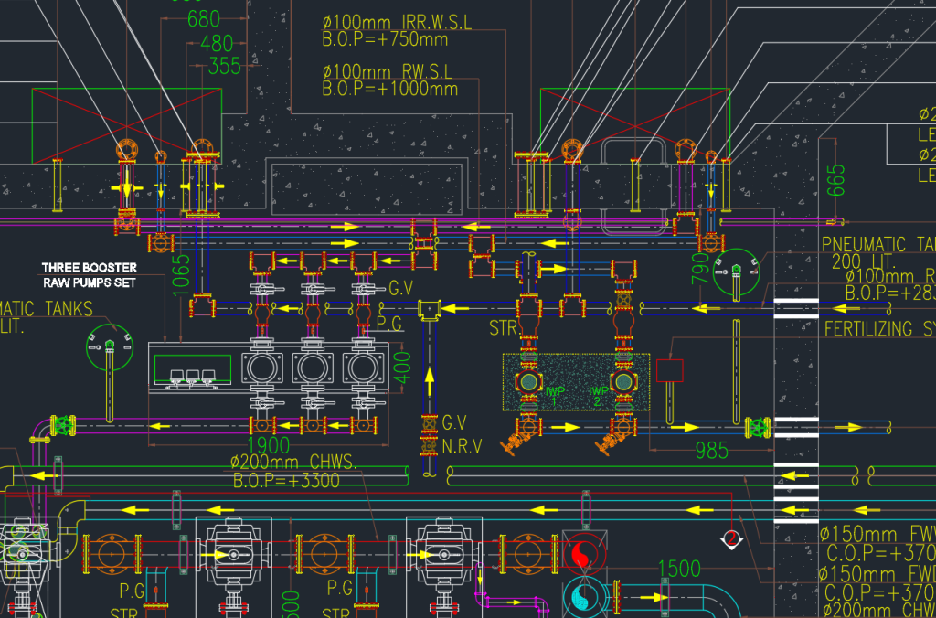
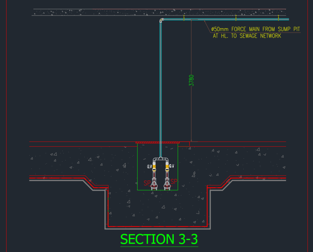
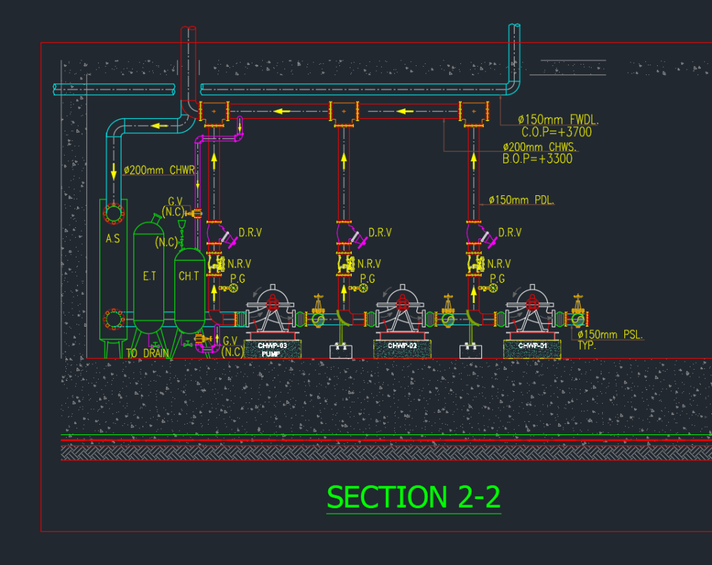
The DWG file includes a floor plan of the mechanical room showing multiple water tanks labeled for fire, domestic, raw, and irrigation purposes. It features comprehensive piping layouts with detailed annotations and valve specifications. Three sectional views illustrate vertical details of pump setups and pipe routing within the room and foundation. Additional close-up sections highlight critical underground pipe connections.
Who can use it
This drawing set is valuable for mechanical engineers, MEP designers, plumbing contractors, and building services consultants engaged in water supply system design and installation. Students and CAD professionals seeking reference for mechanical water system layouts will also find it useful.
Conclusion
Use this downloadable DWG file as a reliable reference for planning and detailing water tank and pump room installations, ensuring coordination and clarity in mechanical building services projects.
Leave a Reply
You must be logged in to post a comment.