
This Floor Mounted Support DWG drawing provides precise dimensional and technical details essential for engineering and construction applications. The drawing is designed to assist engineers, designers, and contractors in planning and executing support installations accurately. With clear labeling and comprehensive views, this CAD file ensures practical usability for structural and mechanical systems that require stable floor-mounted supports.
What the drawing includes
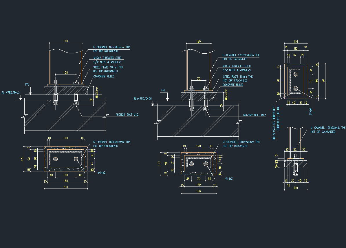
The drawing includes multiple sectional and top views of various floor-mounted support configurations. It shows the U-channel dimensions, steel plate thickness, anchor bolt placements with threading specifications, and concrete fill details. Each view is annotated with clear measurements such as width, height, and thickness in millimeters, along with material callouts indicating hot dip galvanization treatments. This detailed layout highlights anchor bolts M12, nut and washer assemblies, and the spatial relationship between components relative to the finished floor level (FFL).
Who can use it
This floor-mounted support drawing is essential for civil and structural engineers, mechanical designers, construction contractors, and CAD technicians. It serves well in designing industrial support systems, plant equipment installation, and structural anchoring projects. Anyone involved in detailing or verifying support base assemblies in building or facility projects will find this CAD file practical for reference or integration.
Conclusion
Use this Floor Mounted Support DWG drawing as a reliable technical reference for your next project requiring detailed support base designs. Download the CAD file to streamline your workflow and ensure precision in your engineering documentation.
Leave a Reply
You must be logged in to post a comment.