
What Is a VRF Condensing Unit?
A VRF (Variable Refrigerant Flow) condensing unit is the heart of a VRF air-conditioning system. It controls the flow of refrigerant to multiple indoor units, allowing simultaneous cooling or heating across zones.
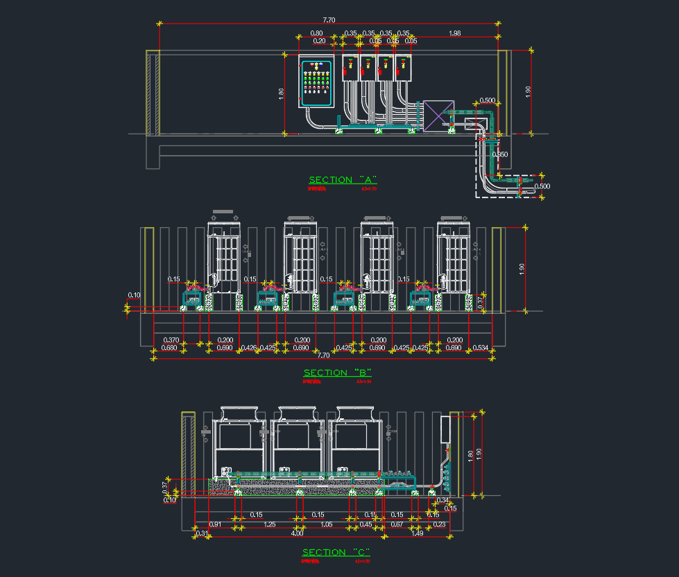
In AutoCAD drawings, a VRF condensing unit is represented as a compact HVAC block placed on the mechanical roof plan or equipment layout.
These units are popular in commercial, residential, and mixed-use buildings because they offer energy efficiency, flexibility, and modular expansion.
Main Components
A complete VRF condensing unit typically includes:
- Compressor modules – variable-speed inverter-driven compressors.
- Refrigerant piping connections – suction and discharge lines.
- Electronic expansion valves – maintain refrigerant flow balance.
- Control boards – manage communication between outdoor and indoor units.
- Fan and coil assembly – air-cooled heat exchange unit.
AutoCAD Block Information
The VRF Condensing Unit DWG block contains:
- Top and front views with standard HVAC layer naming.
- Accurate connection points for liquid and gas piping.
- Dimension reference for unit placement and coordination.
- Editable attributes for equipment tag, capacity, and manufacturer.
It’s compatible with AutoCAD 2010 and above, as well as DraftSight and BricsCAD.
Application in Design
VRF systems are ideal for:
- Office buildings and hotels with variable load requirements.
- Apartments or villas needing zone control.
- Retrofit projects where ductwork is limited.
Using standardized DWG blocks for the condensing unit ensures consistent symbol usage and easier coordination with mechanical and electrical layouts.
How to Use
- Download the DWG file.
- Insert it into your HVAC equipment layout.
- Connect refrigerant lines to indoor units via Y-joint fittings.
- Add annotation tags for capacity (e.g., 8HP, 10HP).
- Include reference to manufacturer (Daikin, Mitsubishi, LG, etc.).
Leave a Reply
You must be logged in to post a comment.