Understanding Electrical Symbols in AutoCAD and DWG Libraries
Electrical symbols are crucial components in the world of CAD design, offering standardized representations of electrical devices and systems within AutoCAD and DWG libraries. For engineers, CAD designers, and architects, the accurate use of electrical symbols ensures consistency, clarity, and compliance in electrical schematics and construction documentation.
What Are Electrical Symbols?
Electrical symbols are graphical representations of electrical and electronic devices, equipment, and functions. These symbols are used in AutoCAD drawings and DWG files to depict components such as switches, outlets, circuit breakers, transformers, lighting fixtures, and more. Using standardized electrical symbols allows for seamless communication between project stakeholders, from design teams to contractors.
Importance of Electrical Symbols in CAD Design
The application of electrical symbols in CAD software like AutoCAD streamlines the design process and minimizes errors. Here are some key benefits:
– Clarity: Electrical symbols convey complex information concisely, reducing the risk of misinterpretation on job sites.
– Standardization: Industry standards, such as IEC, ANSI, and IEEE, ensure that symbols are universally understood.
– Efficiency: Pre-built symbol libraries in DWG format allow designers to quickly insert and modify elements, boosting productivity.
– Compliance: Using standard electrical symbols helps meet regulatory requirements and code compliance.
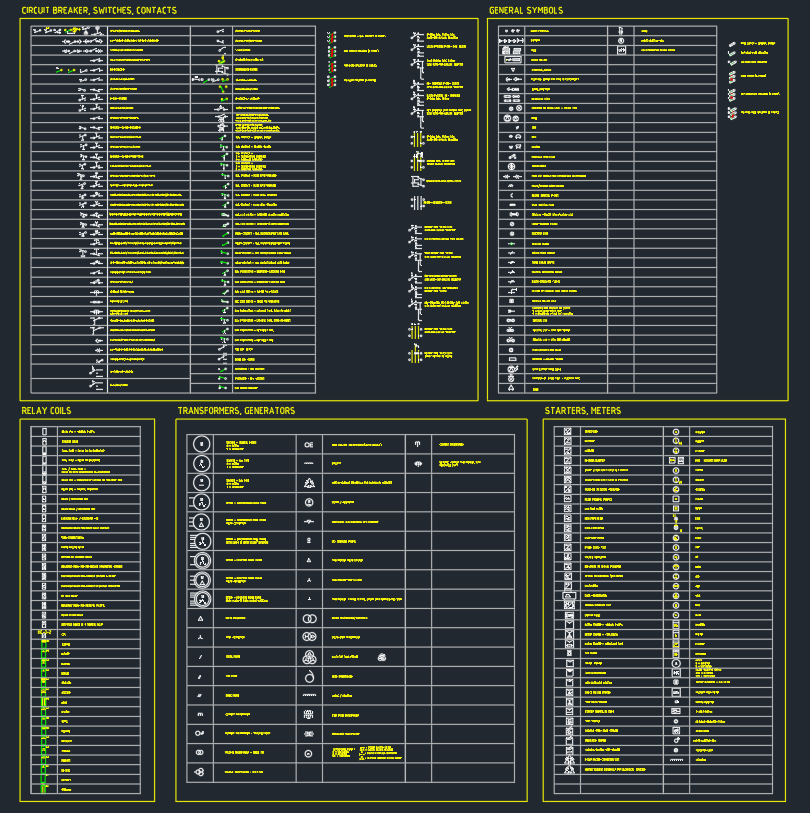
Common Electrical Symbols in AutoCAD & DWG Libraries
AutoCAD and DWG libraries offer an extensive range of electrical symbols for various project needs. Some of the most commonly used electrical symbols include:
– Switches: Single-pole, double-pole, three-way, and four-way switches.
– Outlets: Duplex, GFCI, and specialty outlets.
– Lighting Fixtures: Ceiling, wall, recessed, and emergency lighting.
– Circuit Breakers: Single and multi-pole breakers, fuses, and disconnect switches.
– Wiring Devices: Junction boxes, terminal blocks, and conduits.
– Grounding: Ground symbols for protective earth and signal ground.
Utilizing these electrical symbols within AutoCAD drawings ensures that the design intent is clear and all components are accurately represented.
How to Use Electrical Symbols in AutoCAD
1. Access the Symbol Library: Most AutoCAD and DWG libraries come pre-loaded with standard electrical symbols. Designers can also import custom symbol blocks to meet specific project requirements.
2. Insert Symbols: Use the “Insert” or “Block” command to place symbols in the drawing. Ensure symbols are scaled correctly and aligned with other drawing elements.
3. Label and Annotate: Always label electrical symbols with tags or descriptions for easy identification. Annotations help contractors and field engineers interpret the drawings accurately.
4. Layer Management: Assign electrical symbols to specific layers for better control over visibility and plotting.
5. Maintain Standards: Adhere to industry standards such as IEC 60617 or ANSI Y32.2 for symbol shapes and meanings.
Best Practices for Electrical Symbols in CAD Projects
– Consistency: Use a consistent set of symbols throughout all project drawings to avoid confusion.
– Verification: Cross-check each electrical symbol with the project legend and specifications.
– Updates: Regularly update your DWG library to include new or revised symbols as standards evolve.
– Documentation: Provide a symbol legend or key on each drawing sheet for quick reference.
Optimizing Electrical Symbols for Project Success
Optimizing your electrical symbols in AutoCAD and DWG libraries not only enhances the professionalism of your drawings but also improves project workflow. Well-organized symbol libraries save time, reduce errors, and facilitate collaboration between team members.
By leveraging high-quality DWG electrical symbols, engineers, CAD designers, and architects ensure that every aspect of their electrical layout is precise, compliant, and ready for construction. Whether designing residential, commercial, or industrial projects, the effective use of electrical symbols is a critical skill in modern CAD drafting.
Conclusion
In summary, electrical symbols are vital for accurate and efficient electrical drafting in AutoCAD and DWG environments. By understanding, applying, and optimizing electrical symbols, design professionals can deliver clear, code-compliant, and easily interpreted electrical plans. Always utilize standard libraries and stay updated with industry best practices to achieve superior results in your CAD projects.
Please log in or register to download this file.
Leave a Reply
You must be logged in to post a comment.