
Understanding the J Bolt Anchor: Essential Fastening Solution in Construction
When it comes to structural integrity and reliable fastening, the J bolt anchor is a staple component in architectural and engineering projects. Commonly used to secure steel columns or heavy machinery to concrete foundations, the J bolt anchor’s unique design and robust performance make it indispensable for CAD designers, architects, and engineers.
What is a J Bolt Anchor?
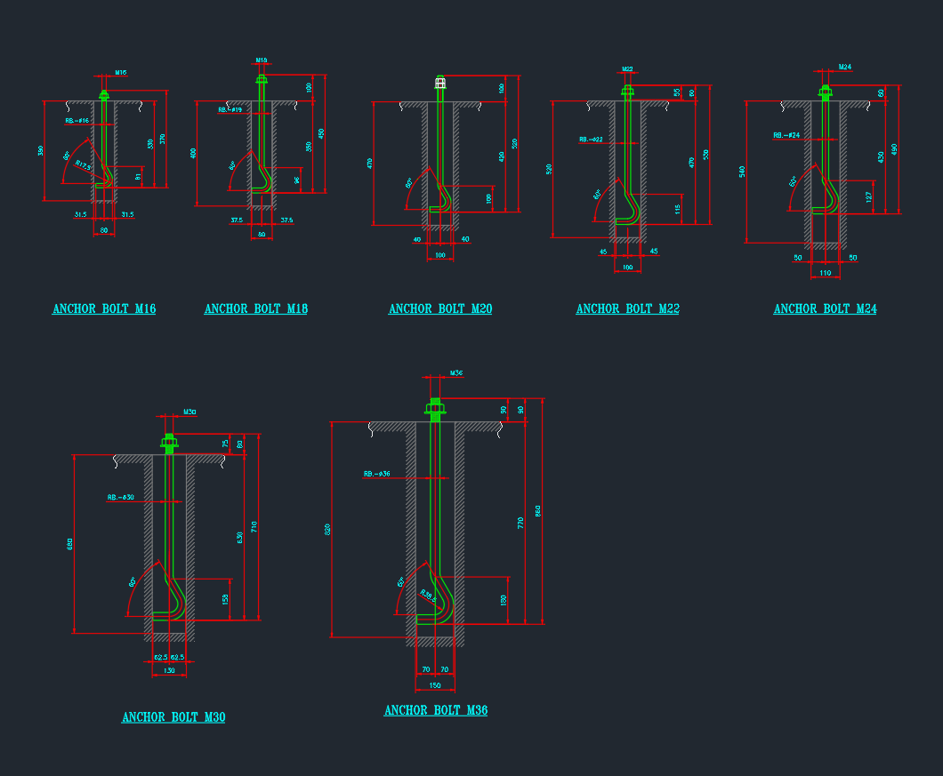
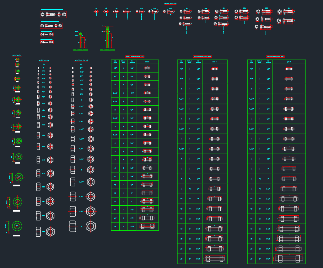
A J bolt anchor is a type of anchor bolt shaped like the letter “J,” which enhances its holding power when embedded in concrete. The long threaded portion above the curve allows for secure attachment of structural elements, while the curved end provides excellent pull-out resistance. J bolt anchors are often specified in AutoCAD and DWG files for foundation plans, base plate connections, and heavy-duty equipment installations.
Key Features of J Bolt Anchors
– Shape: The J-shaped bend increases resistance to tension and shear forces.
– Material: Typically manufactured from carbon steel or stainless steel for strength and corrosion resistance.
– Threading: The threaded end accommodates nuts and washers for a tight, adjustable fit.
– Sizes: Available in a range of diameters and lengths to suit various load requirements.
Applications of J Bolt Anchors in Engineering Design
J bolt anchors are critical in many structural and industrial applications. In AutoCAD and DWG design libraries, J bolt anchor blocks are frequently used for:
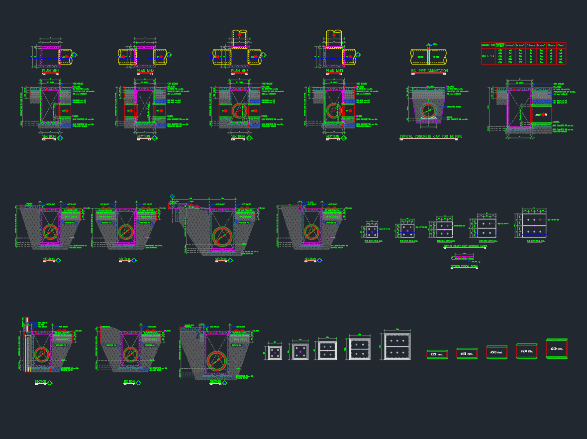
– Securing steel columns to concrete foundations
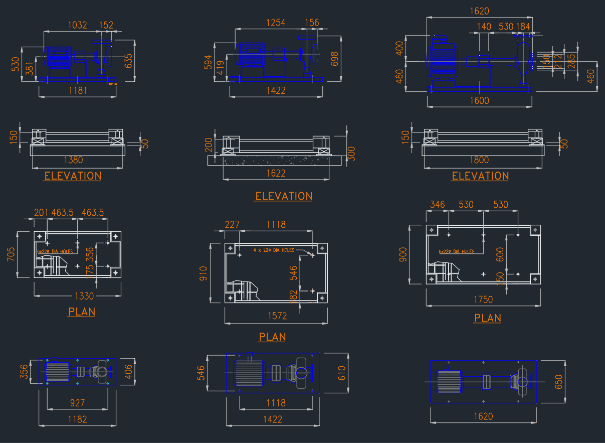
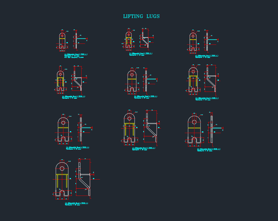
– Anchoring machinery and equipment
– Mounting poles, pipelines, and guardrails
– Supporting structural frameworks in industrial settings
The J bolt anchor is often embedded in wet concrete, with the hook positioned below the surface to prevent extraction under load. CAD designers must ensure accurate placement, spacing, and alignment, which is why incorporating J bolt anchor details into DWG libraries and BIM models is standard practice.
How to Specify a J Bolt Anchor in Your CAD Drawings
When detailing a J bolt anchor in your AutoCAD or DWG project, consider these technical specifications:
– Diameter & Length: Match the J bolt anchor size to the load and embedment depth.
– Thread Length: Ensure sufficient threads are exposed above the concrete for secure fastening.
– Material Grade: Specify stainless steel or galvanized finishes for outdoor or corrosive environments.
– Spacing & Edge Distance: Follow building codes and manufacturer recommendations to prevent concrete cracking.
Including these details in your CAD blocks or dynamic components streamlines the design and construction process and reduces site errors.
Advantages of Using J Bolt Anchors
Superior Holding Power
The curved “J” end of the J bolt anchor offers superior pull-out resistance compared to straight anchor bolts. This makes the J bolt anchor ideal for dynamic and heavy structural loads.
Versatility
J bolt anchors are compatible with a broad range of equipment and base plates. Their adaptability makes them a go-to solution in both standard and custom projects.
Easy Integration with DWG Libraries
For CAD designers, J bolt anchor blocks and dynamic components are readily available in most DWG libraries. Integrating these details into your drawings increases accuracy and efficiency, ensuring every J bolt anchor is correctly positioned and specified.
Tips for Installing J Bolt Anchors
1. Accurate Placement: Use templates or layout drawings to position the J bolt anchor precisely within the formwork before pouring concrete.
2. Alignment: Ensure J bolt anchors are plumb and aligned with the base plate holes.
3. Embedment Depth: Adhere to the specified embedment depth for optimal load transfer and to prevent failure.
4. Inspection: Verify all J bolt anchors are set correctly before the concrete cures.
Conclusion
For engineers, architects, and CAD professionals, the J bolt anchor is a fundamental fastening solution that ensures safety and performance in structural applications. By understanding its properties and integrating precise J bolt anchor details into your AutoCAD and DWG designs, you enhance both the durability and reliability of your projects. Always refer to industry standards and manufacturer guidelines when specifying and installing J bolt anchors to achieve the best results.
Please log in or register to download this file.
Leave a Reply
You must be logged in to post a comment.