
Introduction to Lifting Lugs
Lifting lugs are essential components widely used in engineering and construction for safe and efficient material handling. These devices act as attachment points for lifting slings, chains, or hooks, enabling the secure movement of heavy loads such as steel structures, machinery, and prefabricated elements. In AutoCAD and DWG library contexts, accurate lifting lug blocks and details are crucial for ensuring that CAD designs meet both safety standards and fabrication requirements.
Function and Application of Lifting Lugs
Lifting lugs serve a primary function: to provide a reliable point for lifting equipment to engage with structural or mechanical items. Engineers and CAD designers often incorporate lifting lug details early in the design phase to ensure that equipment can be safely transported, installed, or maintained. Typical applications include:
– Structural steel beams and columns
– Heavy machinery casings
– Pressure vessels and tanks
– Precast concrete components
By incorporating lifting lugs into CAD models and DWG libraries, designers can streamline fabrication drawings, ensuring that every lifting point is properly placed and dimensioned for safe rigging.
Key Design Considerations
When designing or selecting lifting lugs for your projects, several technical factors must be taken into account:
Load Capacity
The primary consideration for any lifting lug is its load capacity. This depends on the material strength, thickness, geometry, and weld size. It is essential to calculate the maximum anticipated load and apply safety factors according to relevant standards (such as ASME, EN, or local codes).
Lug Geometry
The geometry of the lifting lug—including hole diameter, length, and width—affects load distribution and ease of connection. Standardized shapes, such as oblong or circular holes, are often preferred for compatibility with shackles and hooks.
Placement and Orientation
Proper placement of lifting lugs ensures balanced lifting and reduces the risk of tilting or rotation. CAD blocks for lifting lugs should clearly indicate recommended orientations and mounting locations.
Weld Detailing
Accurate weld details are critical for structural integrity. Lifting lugs are typically welded to the parent structure, and the weld size and length must be specified in the DWG drawing. Over-welding or under-welding can lead to failure during lifting operations.
Lifting Lug CAD Blocks and DWG Libraries
For CAD designers and architects, access to high-quality lifting lug blocks in DWG format is invaluable. These blocks save time and help maintain consistency across projects. Key features of effective lifting lug DWG blocks include:
– Scalable and parametric designs
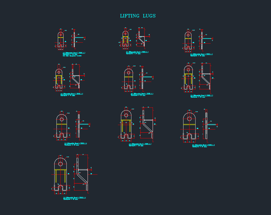
– Clear dimensioning for hole size, plate thickness, and weld details
– Layer management for integration into existing CAD templates
– Annotation for load ratings and identification numbers
When sourcing or creating lifting lug CAD blocks, ensure they comply with industry standards and allow for customization based on specific project needs.
Industry Standards and Best Practices
Adhering to industry standards is vital for safety and compliance. Standards such as ASME BTH-1, EN 13155, and local engineering codes provide guidelines on:
– Material selection
– Minimum and maximum dimensions
– Testing and inspection requirements
– Documentation and marking
Including references to these standards in your DWG library documentation enhances both safety and design quality.
Conclusion
Lifting lugs play a critical role in the safe handling of heavy equipment and structures. For engineers, CAD designers, and architects, understanding the correct design, placement, and annotation of lifting lugs is vital. Incorporating standardized lifting lug blocks into your AutoCAD and DWG libraries ensures efficient workflows, greater safety, and compliance with industry standards.
Optimize your next project by integrating robust lifting lug details into your CAD drawings, and leverage comprehensive DWG libraries for faster, safer, and more accurate engineering designs.
⬇ Download AutoCAD File
Leave a Reply
You must be logged in to post a comment.