
Introduction to Electrical Single Line Diagram of MTS
An Electrical Single Line Diagram (SLD) of MTS is a critical documentation tool for engineers, CAD designers, and architects involved in designing, planning, and maintaining electrical systems with Manual Transfer Switches (MTS). This concise diagram provides a simplified yet comprehensive representation of the power flow and system connections, ensuring efficient communication and safe operation within electrical installations.
What is an Electrical Single Line Diagram of MTS?
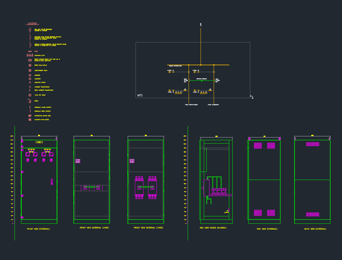
An Electrical Single Line Diagram of MTS illustrates the main components and interconnections in a power distribution system where a Manual Transfer Switch is utilized. The SLD uses standardized symbols to depict circuit breakers, loads, power sources (such as generators and utility supply), and the MTS itself, streamlining complex electrical layouts into an easy-to-read format.
Key Components in the SLD of MTS
– Utility Power Source: Shows the main grid connection.
– Generator: Depicts the backup power source.
– Manual Transfer Switch (MTS): Central to the diagram, indicating the manual operation mechanism for switching between power sources.
– Load Distribution: Outlines the distribution board and critical loads connected to the MTS.
– Protective Devices: Includes fuses, circuit breakers, and earth connections for system safety.
Importance of SLD in Electrical Design
The Electrical Single Line Diagram of MTS serves several essential functions in electrical system design:
– Simplifies Complex Circuits: By reducing multi-wire circuits to a single line, the diagram offers clarity and easy interpretation for engineers and designers.
– Facilitates Maintenance: Maintenance teams rely on SLDs to quickly identify components and interconnections, minimizing downtime during troubleshooting.
– Ensures Safety Compliance: Accurate SLDs are vital for adhering to electrical codes and safety regulations, especially in critical infrastructure projects.
Creating an Electrical Single Line Diagram of MTS in AutoCAD
When drafting an Electrical Single Line Diagram of MTS in AutoCAD, adherence to industry standards is crucial. The process includes:
1. Symbol Selection: Utilize DWG libraries containing standardized electrical symbols for MTS, generators, circuit breakers, and loads.
2. Layer Management: Organize different power sources and loads on separate layers for clarity.
3. Annotation: Clearly label all components, switches, and connection points.
4. Revision Control: Maintain versioning to track design changes throughout the project lifecycle.
Benefits of Using DWG Libraries
– Consistency: Ensures standardization across multiple projects.
– Efficiency: Speeds up the drafting process with ready-to-use blocks and templates.
– Accuracy: Reduces errors by using pre-verified electrical symbols and layouts.
Applications of MTS Single Line Diagrams
The Electrical Single Line Diagram of MTS finds widespread application in various sectors:
– Commercial Buildings: For reliable switching between utility and backup power.
– Industrial Facilities: Ensures seamless operation during power outages.
– Healthcare: Critical for hospitals requiring uninterrupted power supply.
– Residential Projects: Used in high-end housing or estates with backup generators.
Best Practices for SLD of MTS
– Update Regularly: Keep the diagram current to reflect any system modifications.
– Verify Connections: Double-check all connections and symbols before finalizing the drawing.
– Follow Standards: Adhere to IEC, ANSI, or local electrical standards for symbol usage and diagram layout.
Download Electrical Single Line Diagram of MTS DWG Files
Accessing pre-made Electrical Single Line Diagram of MTS DWG files can significantly enhance project efficiency. Reputable DWG library websites offer downloadable templates, enabling engineers and architects to focus on system optimization rather than creating drawings from scratch.
Conclusion
The Electrical Single Line Diagram of MTS is an indispensable resource for engineers, CAD designers, and architects. It not only simplifies complex electrical systems but also ensures safety, compliance, and efficient workflow. Leveraging high-quality DWG libraries for creating these diagrams in AutoCAD further enhances productivity and design accuracy. For any project involving Manual Transfer Switches, a well-crafted SLD is a cornerstone of successful electrical engineering.
⬇ Download AutoCAD File
Leave a Reply
You must be logged in to post a comment.