
Understanding the Electrical Single Line Diagram of MDB
An Electrical Single Line Diagram (SLD) of the Main Distribution Board (MDB) is a critical component in the design and documentation of electrical power distribution systems. For engineers, CAD designers, and architects, the MDB single line diagram provides a simplified graphical representation of a complex electrical system, showing how electrical power flows from the main source to various loads and sub-distribution boards. In this post, we will explore the essential elements, benefits, and best practices for creating and interpreting an Electrical Single Line Diagram of MDB, with a focus on optimizing your AutoCAD and DWG library workflow.
—
What is an Electrical Single Line Diagram of MDB?
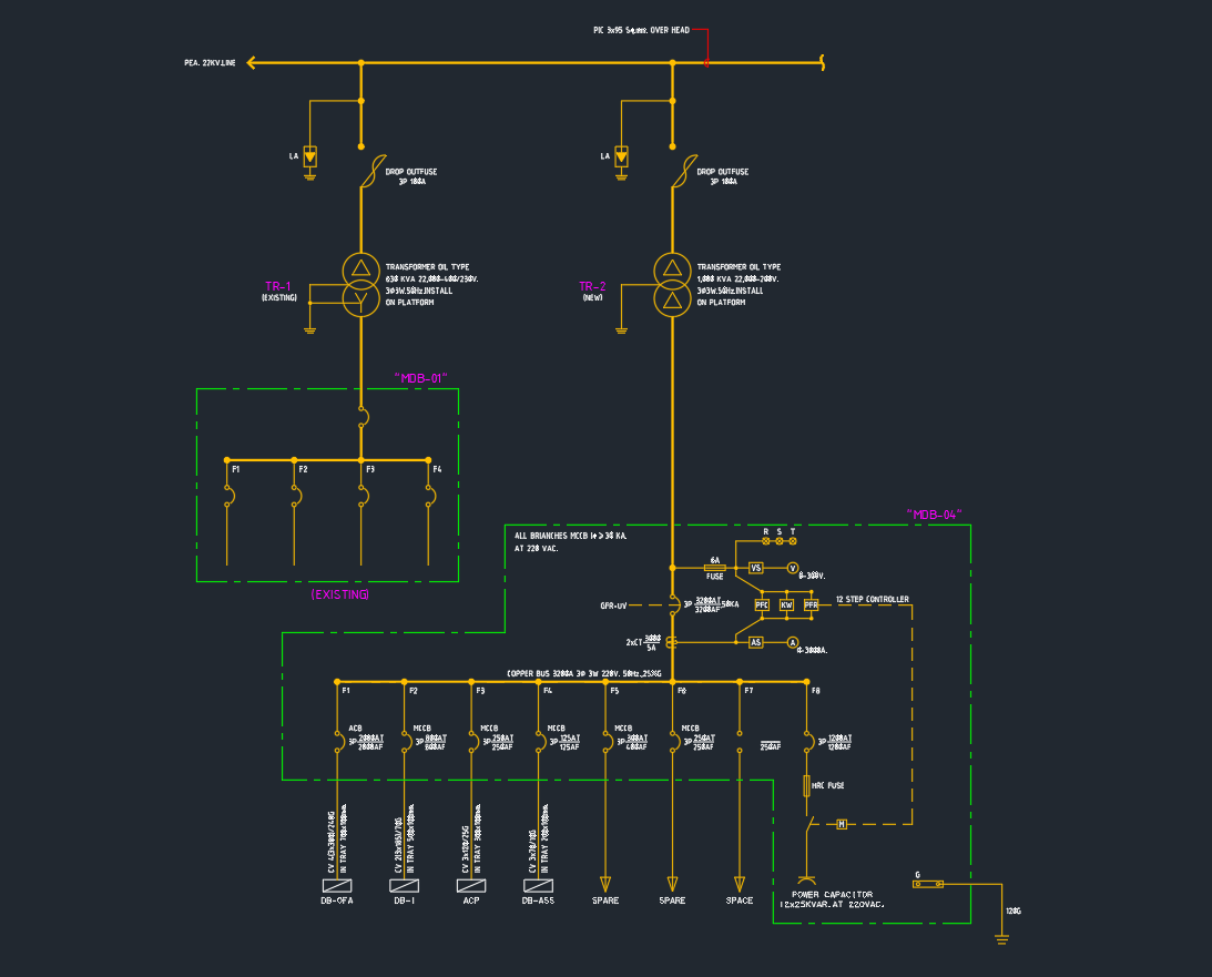
An Electrical Single Line Diagram of MDB is a schematic drawing that uses standard symbols to represent electrical equipment and connections within the main distribution board. Instead of showing every wire and connection, the SLD uses single lines and standardized symbols to convey the entire distribution network efficiently. This diagram typically includes:
– Incoming power supply (utility grid or generator)
– Main circuit breaker
– Busbars
– Outgoing feeders to sub-distribution boards or loads
– Protection devices (MCBs, MCCBs, fuses)
– Meters and monitoring equipment
– Earthing and neutral arrangements
By using an SLD, professionals can quickly assess the design, capacity, and safety of an MDB, making it an indispensable tool in electrical engineering and architectural projects.
—
Key Elements of MDB Single Line Diagrams
When designing or reading an Electrical Single Line Diagram of MDB, it’s essential to understand the following core components:
1. Incoming Power Source
The incoming supply, shown at the top of the SLD, could be from a utility transformer, generator, or both. The connection is typically represented by a single line entering the MDB.
2. Main Circuit Breaker
The main circuit breaker acts as the primary protection device for the entire distribution board. Its rating and type should be clearly marked on the diagram.
3. Busbars
Busbars distribute power to multiple outgoing feeders. The SLD will represent busbars as horizontal or vertical lines connecting different switches and breakers within the MDB.
4. Outgoing Feeders
Each outgoing feeder from the MDB supplies power to either a sub-distribution board or a specific load. The SLD should show the destination, breaker rating, and type for each feeder.
5. Protection Devices
Protection devices, such as MCBs, MCCBs, and fuses, are essential for safe operation. Their types and ratings are depicted using standard symbols, ensuring compliance with electrical standards.
6. Instrumentation and Metering
Meters, ammeters, voltmeters, and other monitoring devices are included to provide real-time data on electrical parameters. These devices enable ongoing maintenance and safety checks.
—
Benefits of Using MDB Single Line Diagrams in AutoCAD and DWG Libraries
Integrating Electrical Single Line Diagrams of MDB into your AutoCAD and DWG library offers several advantages:
– Efficiency: Standardized symbols and templates speed up the design process, reducing errors and rework.
– Clarity: Single line diagrams make it easier for engineers and architects to understand power distribution, especially in complex projects.
– Compliance: Using industry-standard symbols and notations ensures your drawings meet local and international electrical codes.
– Documentation: Well-prepared SLDs provide a reliable reference for installation, commissioning, and future maintenance.
—
Best Practices for Creating MDB Single Line Diagrams
To maximize the utility and accuracy of your Electrical Single Line Diagram of MDB, follow these best practices:
– Use Standard Symbols: Always use internationally recognized symbols for breakers, transformers, meters, and other components. This ensures clarity and compliance.
– Maintain Legibility: Keep your diagram uncluttered. Use clear labels and adequate spacing between elements.
– Layer Management: In AutoCAD, use layers to separate different systems (e.g., power, control, earthing), making the SLD easier to edit and review.
– Consistent Naming: Assign logical names or codes to each feeder, breaker, and load for easy identification.
– Update Regularly: As changes are made to the distribution board, ensure the SLD is promptly updated to reflect the current state.
—
Downloading and Using MDB SLDs from DWG Libraries
Many DWG libraries offer pre-drawn Electrical Single Line Diagrams of MDBs compatible with AutoCAD and other design software. These resources can be customized to fit your specific project requirements, saving valuable design time. Ensure that downloaded SLDs are reviewed for compliance with your project’s voltage, current, and safety standards before integration.
—
Conclusion
The Electrical Single Line Diagram of MDB is an essential tool for engineers, CAD designers, and architects involved in electrical system design. By leveraging standardized SLDs in your AutoCAD and DWG library, you can enhance design efficiency, ensure safety, and maintain compliance with relevant standards. For reliable and efficient project execution, always prioritize well-documented and up-to-date single line diagrams for your main distribution boards.
⬇ Download AutoCAD File
Leave a Reply
You must be logged in to post a comment.