
Understanding the Electrical Single Line Diagram of DB
An Electrical Single Line Diagram (SLD) of a Distribution Board (DB) is a simplified graphical representation of an electrical power system’s distribution network. This essential diagram is widely used by engineers, CAD designers, and architects for planning, installation, and maintenance of electrical systems in residential, commercial, and industrial buildings. Understanding how to read and create a single line diagram of a DB is crucial for ensuring safety, compliance, and operational efficiency.
—
What is an Electrical Single Line Diagram of DB?
An Electrical Single Line Diagram of DB illustrates how electrical power is distributed from the main power supply to various sub-circuits through a distribution board. Unlike detailed wiring diagrams, the SLD uses standard symbols and a single line to represent multiple conductors, making it easier to interpret complex electrical systems with clarity.
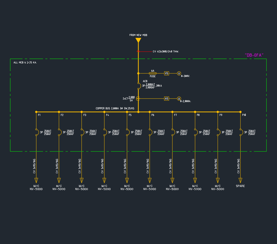
Key elements typically shown in a DB SLD include:
– Incoming main power supply
– Circuit breakers (MCB, MCCB)
– Earth leakage circuit breakers (ELCB or RCCB)
– Busbars
– Outgoing circuits and loads
– Earthing connections
—
Importance of SLD for Distribution Boards
The electrical single line diagram of DB is not just a technical drawing; it is a critical tool for:
– Design Verification: Ensuring all components are correctly rated and coordinated for the load.
– Safety Compliance: Verifying adherence to electrical codes and standards.
– Troubleshooting: Simplifying the identification of faults and maintenance procedures.
– Documentation: Providing clear records for future upgrades, audits, or inspections.
—
Standard Symbols Used in Electrical SLD of DB
Creating or interpreting an electrical single line diagram of DB requires knowledge of standard electrical symbols, such as:
– Lines: Representing conductors or cables.
– Rectangles: Indicating circuit breakers or protective devices.
– Circles: Representing loads like lighting or power outlets.
– Ground/Earth symbols: Showing earthing points.
These symbols are standardized in DWG libraries and are readily available for CAD design, ensuring consistency and precision.
—
Steps to Create an Electrical Single Line Diagram of DB
1. Identify Power Source: Start with the main incoming supply, noting voltage and phase.
2. Draw Main Switch/Breaker: Represent the main protective device connecting the supply to the DB.
3. Add Busbars: Show horizontal or vertical busbars distributing power to outgoing circuits.
4. Insert Circuit Breakers: Place MCBs or MCCBs for individual circuits, indicating their ratings.
5. Show Outgoing Circuits: Draw lines to represent each outgoing circuit (lighting, power, HVAC, etc.).
6. Include Protection and Metering Devices: Indicate surge protectors, energy meters, or RCDs as required.
7. Mark Earthing Points: Clearly show the earthing connections for safety.
—
Best Practices for CAD Designers and Engineers
When drafting an electrical single line diagram of DB in AutoCAD or similar CAD software, follow these best practices:
– Use Standard DWG Blocks: Leverage libraries with pre-defined symbols for accuracy and speed.
– Maintain Readability: Ensure labels and ratings are visible and not cluttered.
– Layer Management: Utilize layers for different systems (power, lighting, earthing) to enhance clarity.
– Consistent Notation: Stick to standard electrical notation as per IEC or local standards.
– Update Documentation: Revise the SLD whenever changes are made to the electrical distribution.
—
Download Electrical Single Line Diagram of DB DWG Files
For engineers and architects looking for ready-made resources, many AutoCAD and DWG library websites offer downloadable electrical single line diagram of DB templates and blocks. These DWG files are compatible with most CAD platforms and are designed for rapid integration into your projects, saving valuable design time while ensuring compliance and precision.
—
Conclusion
The electrical single line diagram of DB is an indispensable tool in electrical system design and maintenance. Mastery of reading and creating SLDs ensures safe, efficient, and compliant electrical distribution in any building project. For professionals working with AutoCAD, utilizing high-quality DWG libraries for SLDs of DB streamlines workflow and enhances the reliability of your electrical documentation. Always prioritize clarity, accuracy, and adherence to standards when working with single line diagrams of distribution boards.
⬇ Download AutoCAD File
Leave a Reply
You must be logged in to post a comment.