
Understanding the Electrical Single Line Diagram of ACP
The Electrical Single Line Diagram (SLD) of ACP is a critical component in the design, analysis, and maintenance of electrical power systems, especially for projects involving Automatic Changeover Panels (ACP). This technical illustration simplifies complex electrical circuits into a single line, providing a clear overview of the power distribution and control mechanisms. For engineers, CAD designers, and architects, mastering the interpretation and creation of electrical SLDs for ACPs is essential for efficient project execution and safety compliance.
What is an Electrical Single Line Diagram of ACP?
An Electrical Single Line Diagram of ACP is a schematic representation that uses single lines and standardized symbols to depict the path of electrical power from the source—such as a generator or utility grid—through the Automatic Changeover Panel to various loads. The ACP is responsible for automatically switching the power source in case of a supply failure, ensuring uninterrupted power to essential systems.
This diagram is not only a design tool but also serves as a reference for installation, troubleshooting, and maintenance. The SLD eliminates the complexity of conventional wiring diagrams by abstracting three-phase conductors and connections into a streamlined, easy-to-understand format.
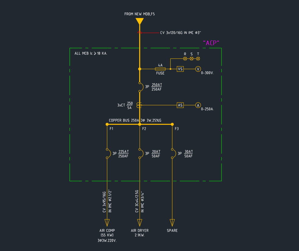
Key Elements of an Electrical SLD of ACP
Understanding the key elements in an Electrical Single Line Diagram of ACP is crucial:
1. Power Sources
– Utility Grid: The primary source of electrical power.
– Generator/Backup Source: Activated by the ACP during utility failure.
2. Automatic Changeover Panel (ACP)
– Main Contactor: Switches between power sources.
– Control Circuit: Monitors supply status and triggers the changeover.
– Indicators and Meters: Display operational status, voltage, and current.
3. Loads
– Essential Loads: Critical systems connected through the ACP.
– Non-Essential Loads: May not be powered during backup operation.
4. Protective Devices
– Circuit Breakers and Fuses: Safeguard the system against overloads and short circuits.
– Earth/Ground Connections: Ensure safety and compliance with standards.
5. Interconnections
– Busbars and Cables: Represented by single lines, showing the flow of electricity between components.
Importance of Electrical SLD in ACP Projects
The Electrical Single Line Diagram of ACP plays a vital role in multiple project phases:
– Design and Planning: Facilitates accurate load calculations, device selection, and cable sizing.
– Installation: Provides installers with a clear guide for wiring and component placement.
– Maintenance and Troubleshooting: Simplifies fault diagnosis and ensures safe operation.
Using an SLD ensures compliance with international electrical standards and helps avoid costly errors during construction and operation.
Best Practices for Creating Electrical SLDs for ACP
To create effective Electrical Single Line Diagrams for ACPs, follow these best practices:
1. Use Standard Symbols: Adhere to IEC or ANSI standard symbols for uniformity.
2. Maintain Clear Labeling: Accurately label all components, power sources, and loads.
3. Include Ratings: Specify voltage, current, and power ratings for all major devices.
4. Indicate Cable Sizes: For precise installation and future upgrades.
5. Highlight Protection Devices: Clearly mark all breakers, fuses, and relays.
6. Show Expansion Provisions: Design with future scalability in mind.
CAD and DWG Libraries for ACP SLDs
CAD designers and engineers benefit from using high-quality DWG blocks and libraries tailored for ACP single line diagrams. These libraries offer standardized symbols and templates, streamlining the drafting process and ensuring compliance with regulatory requirements. Integrating such resources into your workflow enhances the accuracy and efficiency of electrical design documentation.
Conclusion
The Electrical Single Line Diagram of ACP is indispensable for anyone involved in electrical system design, installation, or maintenance. It provides a comprehensive yet simplified view of complex power distribution networks, ensuring reliability and operational safety. By leveraging standardized CAD libraries and adhering to best practices, professionals can create precise and compliant SLDs, ultimately contributing to the success of any project involving Automatic Changeover Panels.
For more CAD blocks and DWG files related to ACP single line diagrams, explore our extensive electrical library—optimized for seamless integration into your next project.
⬇ Download AutoCAD File
Leave a Reply
You must be logged in to post a comment.