
Understanding Electrical Single Line Diagrams for MSB
An Electrical Single Line Diagram (SLD) for Main Switch Board (MSB) is a crucial documentation tool for engineers, CAD designers, and architects working on building electrical systems. This simplified graphical representation illustrates the main electrical distribution path, displaying connections and components using standardized symbols. By focusing on the MSB, the SLD provides a clear overview of how electrical power is distributed and controlled within a facility.
Why Electrical Single Line Diagrams are Essential for MSB
The Main Switch Board (MSB) acts as the primary distribution point for electrical circuits within any commercial or industrial building. Creating a detailed Electrical Single Line Diagram for the MSB ensures:
– Safety: Clearly mapped circuits and protection devices minimize the risk of electrical faults.
– Compliance: SLDs help meet local and international electrical standards (such as IEC, NEC).
– Efficiency: Simplifies troubleshooting, maintenance, and future upgrades.
– Documentation: Provides essential reference for engineers and contractors during installation, inspection, and operation.
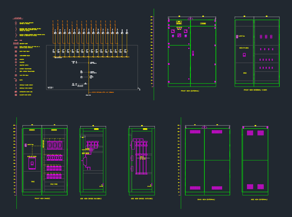
Key Components in an MSB Single Line Diagram
An optimized electrical single line diagram for MSB typically includes these elements:
– Incoming Power Supply: Indicates the main electrical supply, usually from a utility or generator.
– Main Circuit Breaker: Shows the main protection device for the entire system.
– Busbars: Depicts the main current-carrying path distributing power to outgoing feeders.
– Outgoing Feeders: Represents circuits supplying power to various sub-distribution boards, loads, or equipment.
– Protective Devices: Fuses, relays, and surge protection devices are illustrated for each circuit.
– Meters and Instrumentation: Displays voltage, current, and power metering for system monitoring.
– Grounding and Earthing: Essential safety feature shown for the entire MSB.
Best Practices for Creating MSB Single Line Diagrams in AutoCAD
When drafting an electrical single line diagram for MSB in AutoCAD or similar CAD software, follow these best practices:
– Use Standard Symbols: Adhere to IEC, IEEE, or local standards for electrical symbols.
– Layer Management: Organize different circuits and components on dedicated layers for clarity.
– Annotation: Clearly label all components, ratings, and cable sizes.
– DWG Library Utilization: Use pre-built DWG blocks for common components to streamline the process.
– Revision Control: Maintain version history to track updates during design and construction phases.
Download Ready-Made MSB Single Line Diagram DWG Files
To accelerate your design process, download high-quality electrical single line diagram for MSB DWG files from reputable CAD libraries. These files are fully editable and compatible with most AutoCAD versions. Using DWG libraries ensures:
– Consistency: Standardized symbols and layouts across projects.
– Time Savings: Quickly adapt templates to project-specific requirements.
– Accuracy: Reduce errors with pre-verified components.
Applications of Electrical Single Line Diagram for MSB
SLDs for MSB are indispensable in:
– Commercial Buildings: Office towers, hotels, and malls require detailed MSB layouts for reliable power distribution.
– Industrial Facilities: Manufacturing plants rely on robust MSB design for heavy machinery and process safety.
– Infrastructure Projects: Airports, hospitals, and universities depend on comprehensive MSB documentation for compliance and operation.
Conclusion: Enhancing Project Success with Accurate MSB SLDs
A well-designed electrical single line diagram for MSB is fundamental for the success of any electrical engineering project. It streamlines communication, ensures system safety, and supports ongoing operation and maintenance. For engineers, CAD designers, and architects, leveraging DWG libraries and AutoCAD tools will significantly improve the accuracy and efficiency of MSB SLD creation.
Stay ahead in your electrical design projects by incorporating up-to-date, standards-compliant single line diagrams for MSB—ensuring safety, compliance, and long-term reliability.
⬇ Download AutoCAD File
Leave a Reply
You must be logged in to post a comment.