
Introduction to Centrifugal Pumps in Engineering Design
Centrifugal pumps are essential mechanical devices widely utilized in various engineering, architectural, and industrial projects. They play a crucial role in fluid transportation systems, making them a staple component in water supply, HVAC systems, fire protection networks, and process plants. For engineers, CAD designers, and architects, understanding the integration and specification of centrifugal pumps within AutoCAD and DWG libraries is vital for efficient project execution and system reliability.
Working Principle of Centrifugal Pumps
Centrifugal pumps operate based on the principle of centrifugal force. When the pump’s impeller rotates, it imparts kinetic energy to the fluid, converting it into pressure energy as the fluid exits the impeller. This mechanism enables centrifugal pumps to move fluids efficiently from one location to another, making them ideal for applications involving water, chemicals, and various other liquids.
Key Components
– Impeller: The rotating component that transfers energy to the fluid.
– Casing: Encloses the impeller and directs flow.
– Suction and Discharge Nozzles: Entry and exit points for the fluid.
– Shaft: Connects the impeller to the motor.
– Seal or Packing: Prevents leakage along the shaft.
Applications of Centrifugal Pumps in Engineering Projects
Centrifugal pumps are prevalent in many sectors due to their versatility and reliability. Common applications include:
– Water supply and distribution systems
– Heating, Ventilation, and Air Conditioning (HVAC)
– Fire protection systems
– Irrigation and agriculture
– Industrial process plants
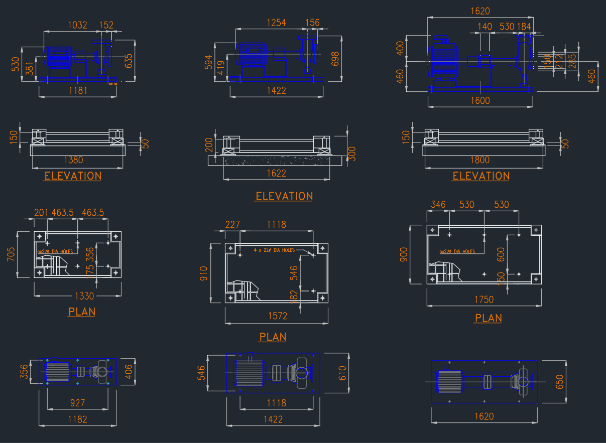
For CAD designers and architects, incorporating centrifugal pump DWG blocks into AutoCAD designs ensures accurate spatial planning and system coordination. These blocks help visualize pump layouts, piping connections, and maintenance clearances, streamlining the design and review process.
Centrifugal Pump Selection Criteria
Selecting the appropriate centrifugal pump requires careful consideration of several factors:
– Flow rate and head requirements
– Fluid properties (temperature, viscosity, corrosiveness)
– System pressure losses
– Pump material compatibility
– Installation environment (indoor, outdoor, hazardous locations)
CAD libraries provide detailed centrifugal pump DWG files, often including manufacturer-specific data, dimensional drawings, and connection details. This ensures precise integration with the overall system design and facilitates accurate documentation for construction and maintenance.
Benefits of Using Centrifugal Pump DWG Blocks in AutoCAD
Utilizing centrifugal pump DWG blocks in AutoCAD offers multiple advantages:
– Enhanced Design Accuracy: Precise representation of pump and piping arrangements.
– Time Savings: Ready-to-use blocks reduce manual drafting efforts.
– Standardization: Ensures consistency across project documentation.
– Improved Collaboration: Facilitates coordination among multidisciplinary teams.
Many reputable DWG library websites offer a wide range of centrifugal pump blocks, including horizontal, vertical, single-stage, and multi-stage variants. These resources help engineers and architects adhere to industry standards and client specifications.
Maintenance and Efficiency Considerations
Proper maintenance of centrifugal pumps is essential for long-term system performance. Regular inspection, lubrication, and alignment checks can minimize downtime and extend equipment lifespan. Efficiency can also be improved by selecting pumps that operate near their best efficiency point (BEP) and by minimizing system losses through optimal piping design.
Conclusion
Centrifugal pumps are indispensable components in modern engineering and architectural projects. Their robust design, versatility, and efficiency make them the preferred choice for fluid handling applications. By leveraging comprehensive DWG libraries and integrating centrifugal pump blocks into AutoCAD workflows, engineers and CAD designers can enhance design quality, streamline collaboration, and ensure successful project delivery. For optimal results, always select the right centrifugal pump for the application and make use of accurate DWG resources to support your engineering designs.
⬇ Download AutoCAD File
Leave a Reply
You must be logged in to post a comment.