
Introduction to Shell and Tube Heat Exchangers
Shell and tube heat exchangers are fundamental components in mechanical engineering, widely used for efficient heat transfer between two fluids. Their robust design, versatility, and reliability make them a preferred choice in various industries, including HVAC, chemical processing, power generation, and oil and gas. For engineers, CAD designers, and architects, understanding the intricacies of shell and tube heat exchangers is essential for effective system design and integration.
What is a Shell and Tube Heat Exchanger?
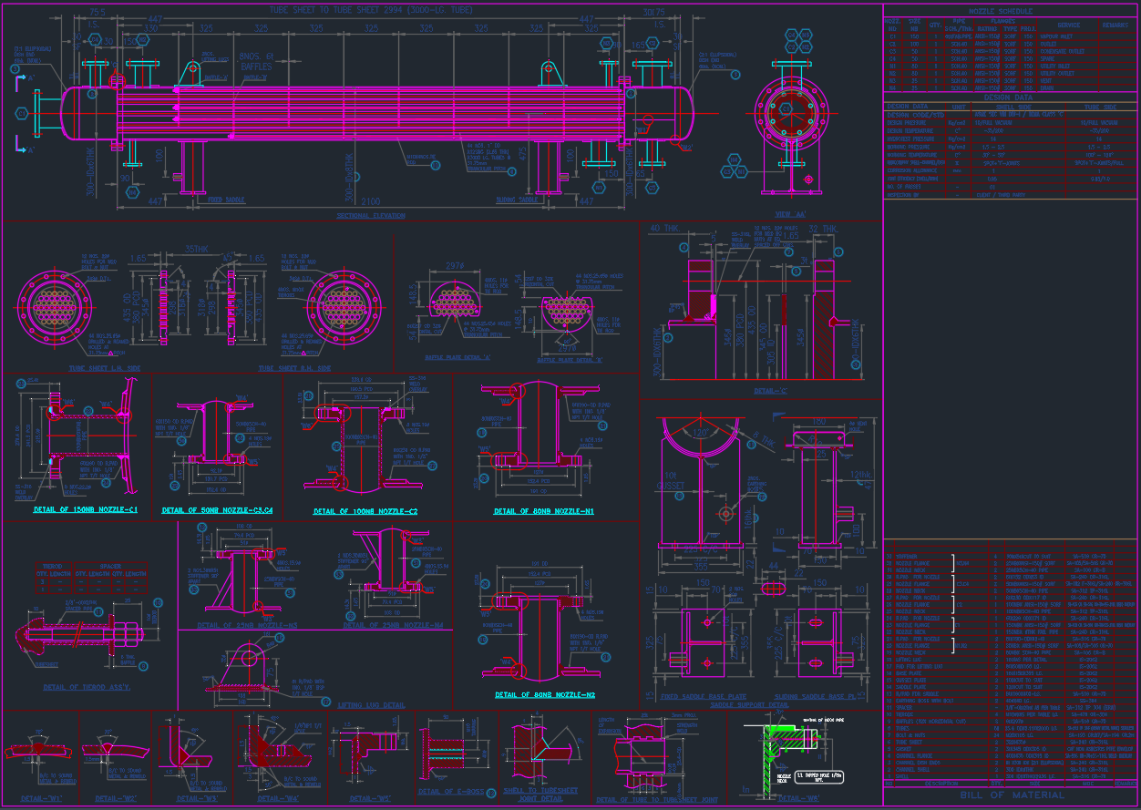
A shell and tube heat exchanger consists of a series of tubes housed within a cylindrical shell. One fluid flows through the tubes, while the other fluid flows around the tubes within the shell. The heat transfer occurs across the tube walls, allowing energy to move from the hotter to the cooler fluid. This design supports high-pressure applications and handles large temperature differences, making it highly efficient and adaptable.
Key Features and Components
Shell
The shell is the outer vessel that contains the tube bundle. It is typically constructed from materials such as carbon steel, stainless steel, or other alloys, depending on the application’s temperature and pressure requirements.
Tube Bundle
The tube bundle comprises several parallel tubes, usually made from thermally conductive materials like copper, stainless steel, or titanium. The tubes can be either straight or U-shaped, depending on the configuration.
Tube Sheets
These are plates that hold the tubes in place at both ends of the shell. Tube sheets ensure the structural integrity and proper alignment of the tube bundle.
Baffles
Baffles are installed inside the shell to direct the flow of the shell-side fluid, enhancing turbulence and, consequently, heat transfer efficiency.
Types of Shell and Tube Heat Exchangers
There are several configurations, with the most common being:
– Fixed Tube Sheet Exchanger: Tubes are fixed at both ends, suitable for applications with minimal thermal expansion.
– U-Tube Exchanger: Tubes are bent into a U-shape, allowing for thermal expansion and easy cleaning.
– Floating Head Exchanger: Allows for differential expansion between the shell and the tube bundle, ideal for high-temperature services.
Applications in Engineering and Architecture
Shell and tube heat exchangers are indispensable in industries requiring thermal management. In HVAC systems, they regulate building temperatures efficiently. In power plants, they condense steam from turbines. Their modularity and adaptability make them suitable for custom CAD modeling and integration into complex systems.
For architects and CAD designers, including accurate shell and tube heat exchanger models in DWG libraries enhances project visualization and streamlines collaboration across disciplines.
Advantages of Shell and Tube Heat Exchangers
– Versatility: Suitable for handling fluids at different pressures and temperatures.
– Scalability: Easily customizable for varying capacities and sizes.
– Durability: Withstands high-pressure and high-temperature environments.
– Ease of Maintenance: Certain configurations allow for straightforward disassembly and cleaning.
Designing Shell and Tube Heat Exchangers in CAD
When designing a shell and tube heat exchanger in AutoCAD or similar CAD platforms, precision is critical. Key parameters include:
– Tube Diameter and Length: Determines the heat transfer area and overall efficiency.
– Tube Pitch: The distance between tubes impacts fluid flow and pressure drop.
– Baffle Spacing: Affects the turbulence and heat transfer coefficient.
– Material Selection: Impacts performance, durability, and maintenance requirements.
Accurate CAD models facilitate seamless integration into larger systems, ensuring compatibility and compliance with industry standards.
DWG Libraries and Shell and Tube Heat Exchangers
Access to comprehensive DWG libraries featuring shell and tube heat exchanger models streamlines the design process for engineers and designers. These libraries provide:
– Pre-drawn 2D: Save time and reduce errors in system layouts.
– Standardized Components: Ensure consistency and adherence to engineering standards.
– Customizable Templates: Allow for quick modifications to suit specific project requirements.
Conclusion
Shell and tube heat exchangers are essential for efficient thermal management in a broad range of engineering applications. Their robust design, adaptability, and widespread availability in DWG libraries make them ideal for integration into CAD-based workflows. By understanding their features, design parameters, and best practices, engineers, CAD designers, and architects can optimize their projects for performance, reliability, and efficiency.
Leave a Reply
You must be logged in to post a comment.